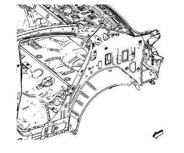
Chevrolet Cruze Repair Manual: Removal Procedure
Warning: Refer to Approved Equipment for Collision Repair Warning in the Preface section.
Warning: Refer to Collision Sectioning Warning in the Preface section.
Warning: Refer to Glass and Sheet Metal Handling Warning in the Preface section.
- Disable the SIR System. Refer to SIR Disabling and Enabling.
- Disconnect the negative battery cable. Refer to Battery Negative Cable Disconnection and Connection.
- Remove all related panels and components.
- Visually inspect the damage. Repair as much of the damage as possible.
- Remove the sealers and anti-corrosion materials from the repair area, as necessary. Refer to Anti-Corrosion Treatment and Repair.

- Create cut lines on the body lock pillar upper reinforcement (1).

Note: Do not damage any other panels or reinforcements.
- Cut the panel where sectioning is to be performed.

- Locate and mark all the necessary factory welds of the body lock pillar upper reinforcement.
- Drill all factory welds. Note the number and location of welds for installation of the service assembly.

- Remove the damaged body lock pillar upper reinforcement.

- Create cut lines on the body side inner panel.

Note: Do not damage any other panels or reinforcements.
- Cut the panel where sectioning is to be performed.

Note: Drill hidden factory welds where body side outer rear panel drain gutter (1) and body side inner panel overlap.
- Locate and mark all the necessary factory welds of the body side inner panel.
- Drill all factory welds. Note the number and location of welds for installation of the service assembly.

- Remove the damaged body side inner panel.
 Body Side Inner Panel Sectioning (MAG-Welding)
Note: According to different corrosion warranties, only the
regional mandatory joining methods are allowed. ...
 Installation Procedure
Remove rear end upper panel extension (1) from service part.
Cut
Cut the body side inner panel in corresponding locations to fit the
remaining original panel. The sectioning jo ...
Other materials:
Forward Lamp Wiring Harness Replacement
Preliminary Procedures
Remove the front bumper. Refer to Front Bumper Fascia Replacement.
Remove the headlamp. Refer to Headlamp Replacement.
Using a scan tool, check for DTCs.
Forward Lamp Wiring Harness
Tip
Create a work area large enough to lay out the new and old wiring
ha ...
Filling a Portable Fuel Container
WARNING
Filling a portable fuel container while it is in the vehicle can cause fuel
vapors that can ignite either by static electricity or other means. You or others
could be badly burned and the vehicle could be damaged. Always:
• Use approved fuel containers.
• Remove the container from the ...
Installation Procedure
Position the front brake shield (2) and front wheel bearing/hub (1)
assembly in the steering knuckle.
Caution: Refer to Fastener Caution in the Preface section.
Install the NEW front wheel bearing/hub bolts (1).
Tighten the bearing/hub bolts (1) in 3 passes. Use the EN-45059 k ...
