Chevrolet Cruze Repair Manual: Stabilizer Shaft Replacement
Special Tools
- CH 904 Underframe
- CH 49289 Centering Adapter
- EN 45059 Torque Angle Sensor Kit
For equivalent regional tools, refer to Special Tools.
Removal Procedure
- Turn the front wheels to the straight forward position and secure the steering wheel from moving.
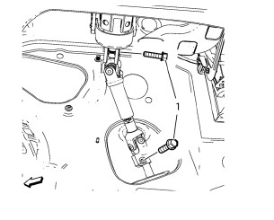
- Remove the 2 lower steering intermediate shaft bolts (1).
- Remove the steering intermediate shaft from the steering gear.
- Raise and support the vehicle. Refer to Lifting and Jacking the Vehicle.
- Remove the tire and wheel assemblies. Refer to Tire and Wheel Removal and Installation.
- Remove the front compartment insulator, if equipped. Refer to Front Compartment Insulator Replacement.
- Remove the exhaust flexible pipe. Refer to Exhaust Flexible Pipe Replacement.
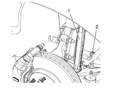
- Remove lower stabilizer link shaft nut (2) on both sides.
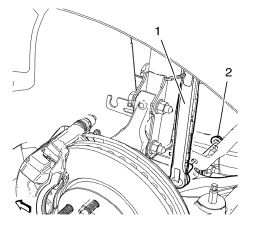
- Remove stabilizer link shaft (1) from stabilizer shaft.
- Remove stabilizer link shaft (1) from stabilizer.

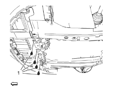
- Remove 4 fasteners (1) of engine side cover on both sides.
.
- Remove 4 fasteners (1) of front en 12. gine compartment cover.
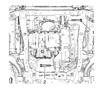
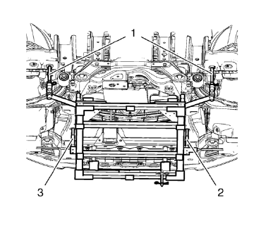
- Remove the front (1) and the rear (2) transmission mount bracket bolts.

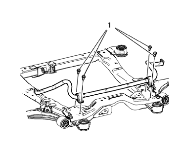
- Remove and DISCARD 2 rear suspension frame bolts (2).
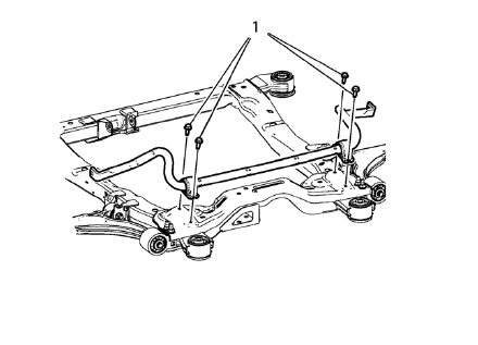
Remove rear frame reinforcements (1).

- Position and set hydraulic lifter in connection with CH-904 frame and CH-49289-50 adapter (2) onto suspension frame (1). Pull away front engine compartment cover slightly..
- Lower suspension frame max. 55 mm.
- Remove the 4 front stabilizer shaft insulator clam bolts (1).
- Remove the stabilizer shaft.
Installation Procedure
- Install the stabilizer shaft.
Caution: Refer to Fastener Caution in the Preface section.
- Install the 4 front stabilizer shaft insulator clam bolts (1) and tighten to 22 N·m (17 lb ft) plus 30 degrees.
- Move out the positioning pins (1) of CH 49289 adapter .
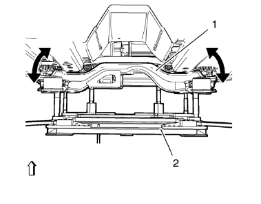
- Raise the frame (1) carefully, 4. using CH 49289 adapter (2).

Note: Note: Do NOT reuse old bolts
- Install the 2 frame reinforcements (1).
- Install the 2 NEW frame rear bolts (2) and tighten to 160 N·m (119 lb ft).
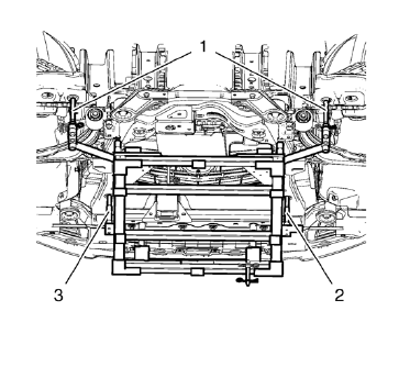
- Install the front transmission mount bolt (1) and tighten to 58 N·m (43 lb ft).
- Install the rear transmission mount bracket bolt (2) and tighten to 100 N·m (74 lb ft).

- Install and tighten 4 fasteners (1) of engine side cover on both sides.
- Install and tighten the 4 fasteners (1) of front engine compartment cover.
- Install the front compartment insulator, if equipped Front Compartment Insulator Replacement.
- Install the exhaust flexible pipe. Refer to Exhaust Flexible Pipe Replacement.
- Install and tighten lower stabilizer link shaft nut (2) on both sides to 35 N·m (26 lb ft).
- Lower the vehicle.
- Install the tire and wheel assemblies. Refer to Tire and Wheel Removal and Installation.
 Front Suspension
Specifications
Front Suspension Components
Drivetrain and Front Suspension Frame
Front Stabilizer Shaft
Drivetrain and Front Suspension Frame Rear Insulator
Front Stabilizer Shaft L ...
 Stabilizer Shaft Link Replacement
Preliminary Procedure
Raise and support the vehicle. Refer to Lifting and Jacking
the Vehicle.
Remove the front tire and wheel assemblies. Refer to Tire and Wheel
Removal a ...
Other materials:
Front Brake Rotor Replacement
Special Tools
CH-41013 Rotor Resurfacing Kit
CH-42450-A Wheel Hub Resurfacing Kit
For equivalent regional tools, refer to Special Tools.
Removal Procedure
Warning: Refer to Brake Dust Warning in the Preface section.
Raise and support the vehicle. Refer to Lifting and Jacking ...
Climate Control Systems
The heating, cooling, defrosting, and ventilation for the vehicle can be controlled with these systems.
Vehicles without Air Conditioning
1. Temperature Control.
2. Bi-level Air Mode.
3. Floor Air Mode.
4. Vent Air Mode.
5. Fan Control.
6. Driver and Passenger Heated Seats (If Equ ...
Front Bumper Impact Bar Replacement
Removal Procedure
Warning: Refer to Approved Equipment for Collision Repair Warning in the
Preface section.
Warning: Refer to Glass and Sheet Metal Handling Warning in the Preface section.
Disable the SIR System. Refer to SIR Disabling and Enabling.
Disconnect the negative battery ...
